Reliance SCADA in Istanbul

Plc Panel Wiring Diagram, http//bookingritzcarlton.info/plcpanelwiringdiagram/ Electrical
location wiring diagrams also evolved into the relay logic being shown in a ladder fashion. The control power hot wire would be the left rail, with the control power neutral as the right rail. The various relay contacts, pushbuttons, selector switches, limit switches, relay coils, motor starter coils, solenoid

Wiring Diagram Of Plc Pdf
How to PLC Control Panel wiring Power Process 337 subscribers Subscribe No views 1 minute ago #PLCControlPanel #IndustrialAutomation #ElectricalEngineering In this comprehensive video.
μέγα κύμα μακιγιάζ ζεστός electrical panel board drawing πακέτο χιούμορ δυσφορία
Wiring Diagrams of PLC and DCS The below list shows the basic types of wiring connections available for DI, DO, AI, and AO Signals: Digital Input (DI) Signals Single-wire Connection Two-wire connection Two-wire connection with Line Monitoring DI with Relay - Wet Contact DI with Relay - Dry Contact

Micro820 Plc Wiring Diagram, http//bookingritzcarlton.info/micro820plcwiringdiagram
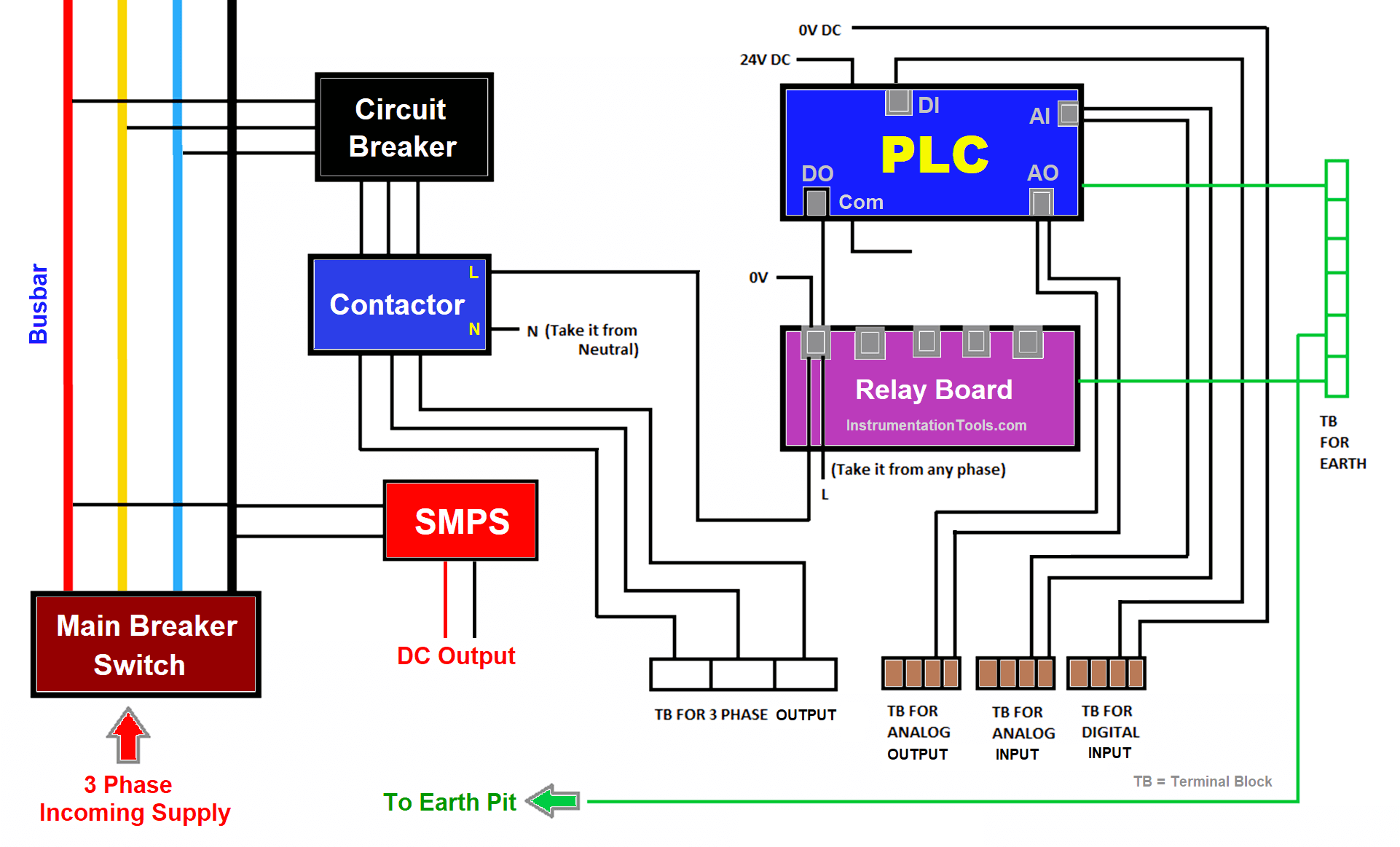
by Viral Nagda In this article, you will learn the wiring in a PLC control panel and the basic electrical design of a PLC system cabinet. Wiring in a PLC control panel is a hectic job and requires a good understanding of PLC standards as well as electrical standards.
Ban genius sunset plc layout
Wiring diagram. Now you maybe be curious how you should know which input on the PLC you should connect the Emergency-Stop to. Well, this is simply done based on the wiring diagram. In a later article, we will get into the details of the wiring diagram and show you how simple it is to read and carry out the control panel wiring.

How to Follow an Electrical Panel Wiring Diagram RealPars
Vladimir Romanov Electrical panel wiring diagrams are used to outline each device, as well as the connection between the devices found within an electrical panel. As electrical panels are what will contain control systems, panel wiring diagrams are commonly encountered by PLC technicians and engineers.

Reliance SCADA in Istanbul
PLC control wiring diagrams have been used in the industrial automation industry for decades. They are often used in conjunction with other control systems such as SCADA, HMI, and DCS. The ability to connect multiple control systems in a single wiring diagram allows technicians to easily create large, complex systems without having to build.

PLC Panel Wiring Service in Chennai, Padi by Automachine Integration System ID 12658967591
A PLC panel is simply an electrical control panel consisting of electrical components which use electric power to control a variety of mechanical functions of industrial machinery or equipment. In order for industrial machinery and equipment to accomplish their various process goals, they require user-defined functions and well-organized control.
Electrical Panel Wiring Diagram
Plc Panel Wiring Diagram Symbols: Understanding the Language of Automation As automation continues to revolutionize commercial and industrial operations, the ability to read and understand Plc Panel Wiring Diagrams is an ever more critical skill. These diagrams are used to represent the wiring of a control system and make it easier for technicians to diagnose, troubleshoot, and work with new.
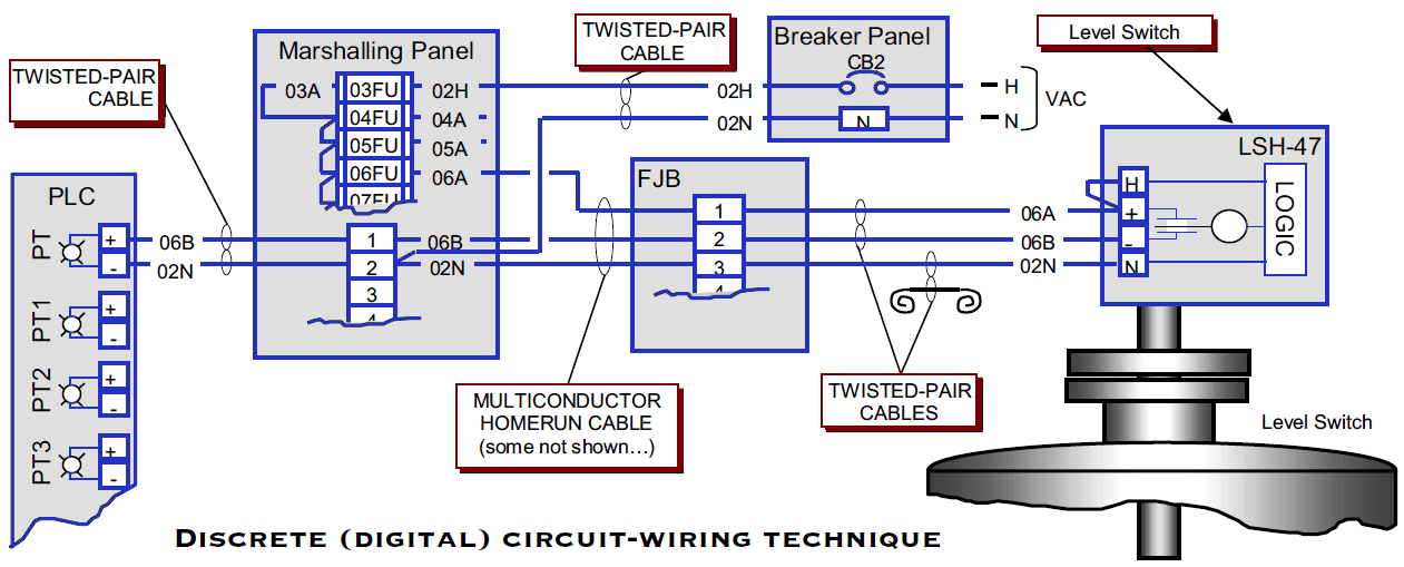
PLC Wiring Diagrams PLC Digital Signals Wiring Techniques
How to Read a PLC Wiring Diagram (Control Panel Wiring Diagram) - Upmation How to Read a PLC Wiring Diagram? In this article, you'll learn how to read, understand and use a PLC wiring diagram. Reading a PLC Wiring Diagram is one of the must-to-learn skills for every automation and electrical engineer.
Gmos Lan 02 Wiring Diagram Download Wiring Diagram Sample
Control Panels compliant with IEC Standards and European Directives 6 Reference Manual, 10/2017, A5E38284819002A/RS-AB/002 Authors Martin Berger Staatlich geprüfter Techniker (state-certified technician) Application consulting and business development for control panel engineering and low - voltage controls and distribution
Plc Wiring Standards
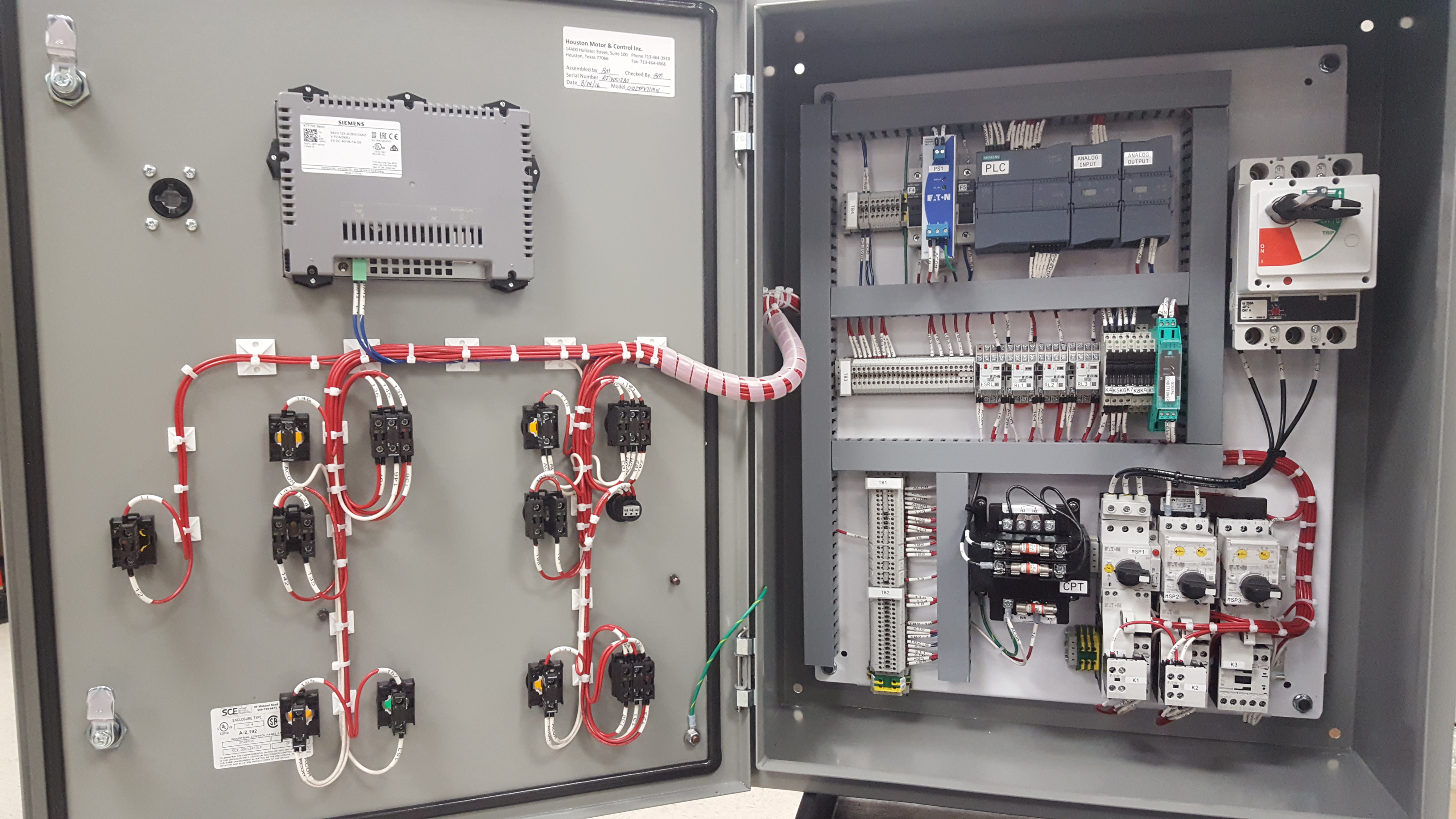
It is a 2-door control panel on the front of which we have some switches that are connected to the PLC inputs and outputs. We are going to look at these switches and try and figure out the.
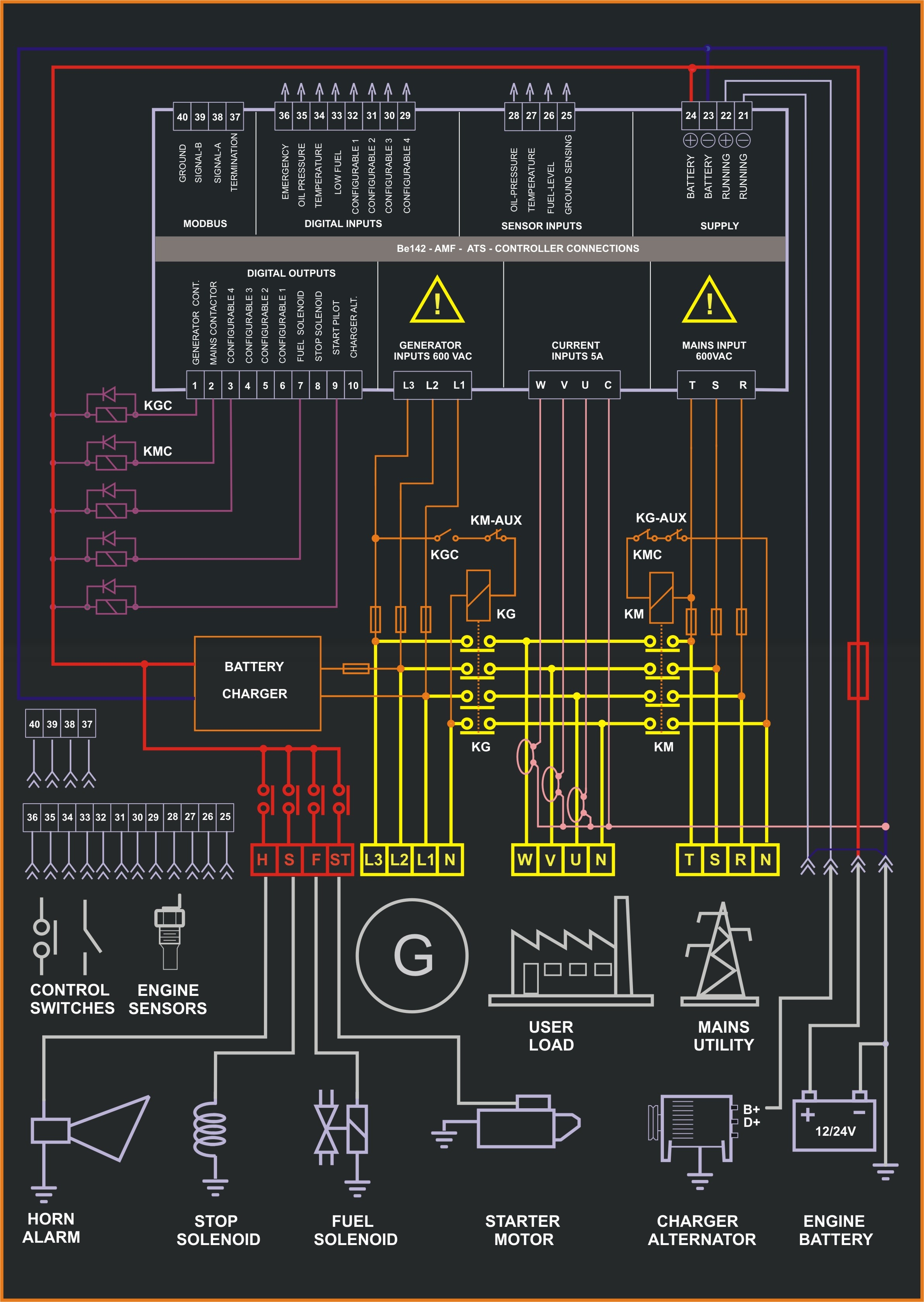
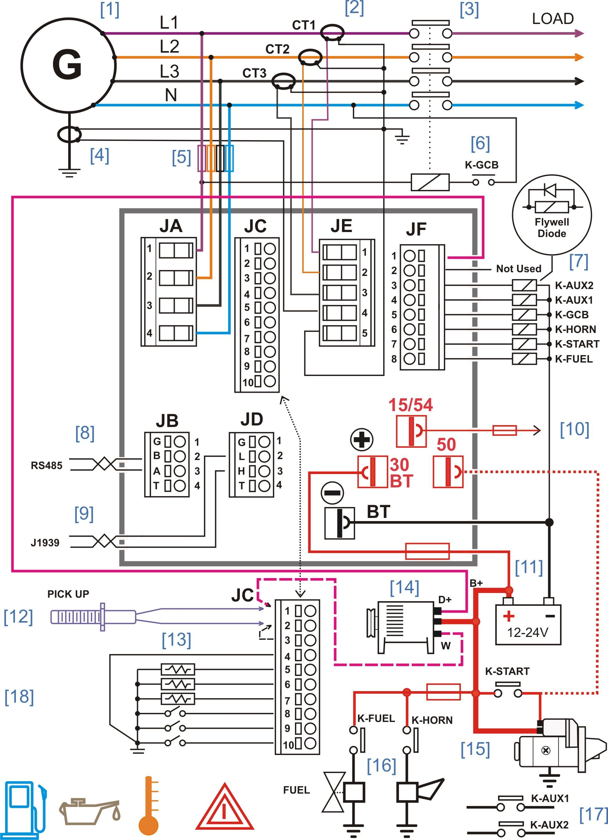
Fg Wilson 2001 Control Panel Wiring Diagram Pdf Wiring Diagram
0:00 / 11:42 • What will you learn in this video? How to Draw a Wiring Diagram and Turn it into a PLC Program (EPLAN Tutorial) Reverse Forward Starter Upmation 164K subscribers Join Subscribe.

PLC wiring diagram. Download Scientific Diagram
What is PLC Control Panel Wiring? PLC Control Panel Wiring refers to the process of connecting various electrical components, such as switches, relays, and sensors, to a programmable logic controller (PLC) in order to control and monitor different machinery or processes.

Plc Relay Wiring Diagram
The following considerations will facilitate an orderly installation of a PLC: PLC I/O module installation Wiring considerations Recommended wiring procedures Wire size Wire and terminal labeling Wire bundling Special I/O connection precautions Connecting leaky inputs Suppression of inductive loads Fusing outputs Shielding I/O module installation

Plc Wiring Diagram Guide Pdf
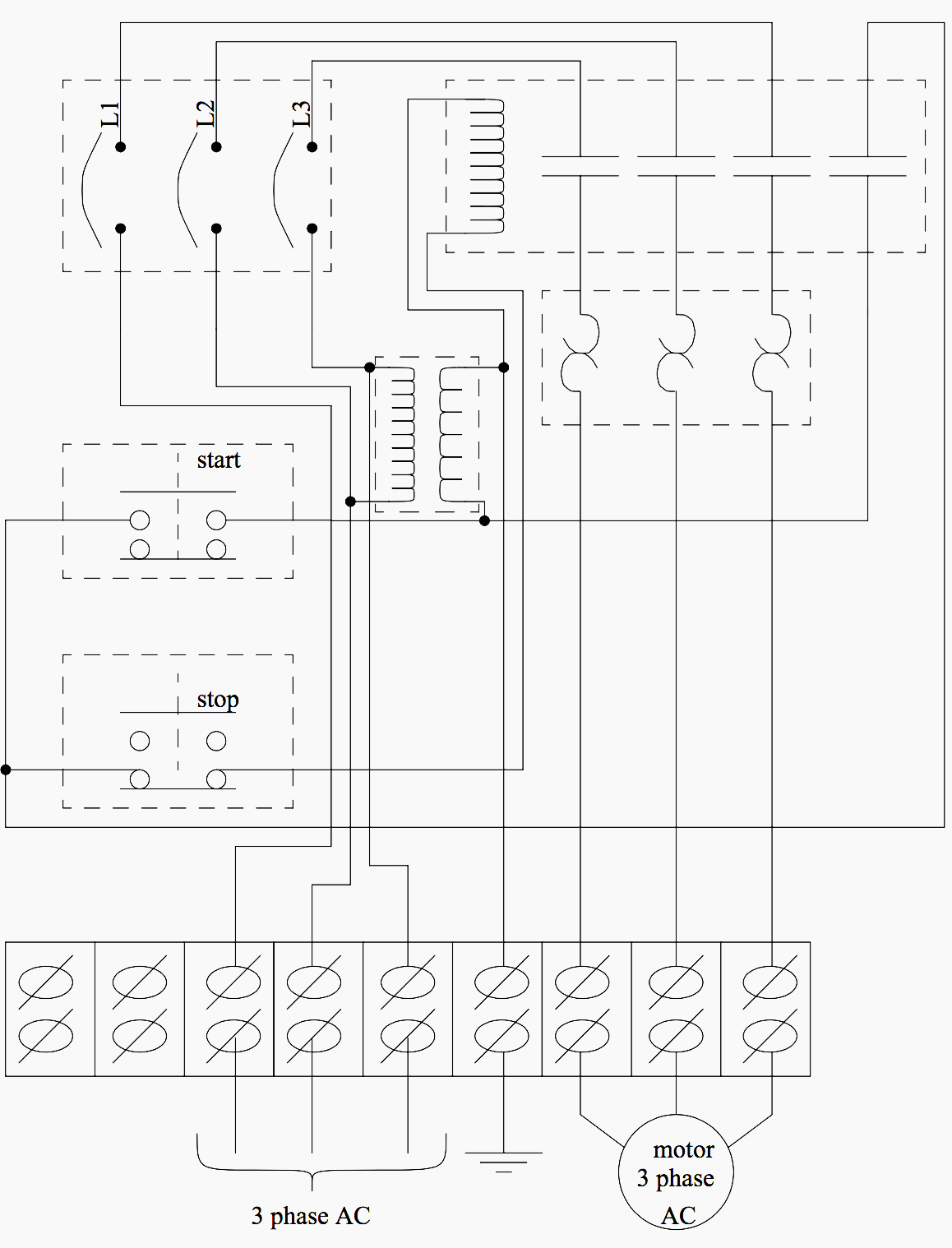
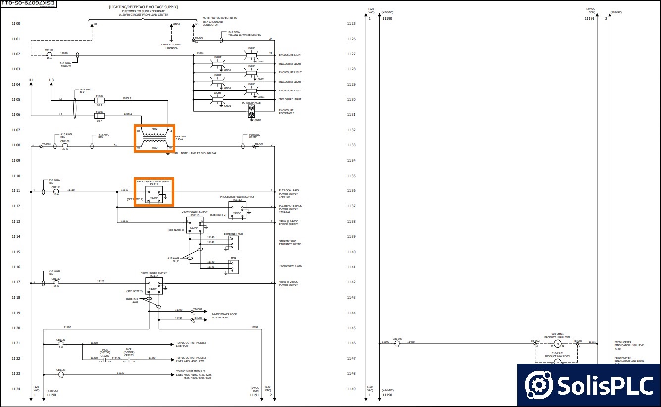
Electrical wiring diagrams of a PLC panel In an industrial setting a PLC is not simply "plugged into a wall socket". The electrical design for each machine must include at least the following components. Transformers - to step down AC supply voltages to lower levels
